ES-150U
Master Clock System Switcher
Click Image to Enlarge
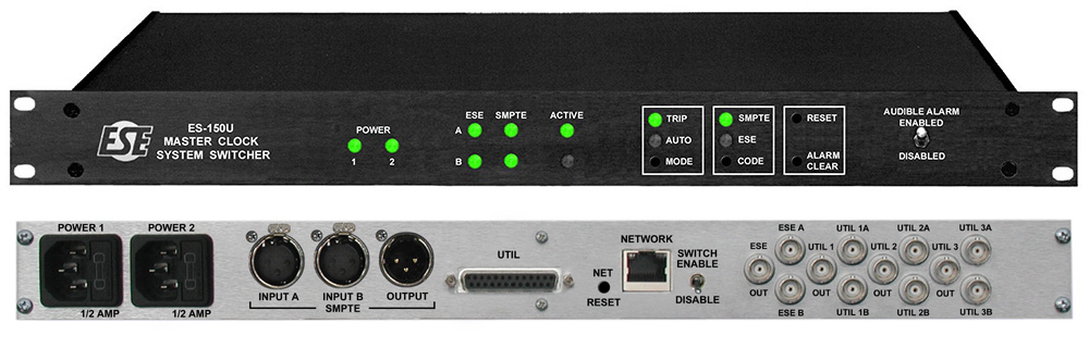
The ES-150U is a Master Clock Switcher. Master Clock Switchers are typically used with a Primary Master Clock (‘A’) and a Secondary Master Clock (‘B’). Master Clock Switchers provide a convenient way of switching to the Secondary Master Clock if a problem develops with the Primary Master Clock. The Master Clock Switcher monitors one or more of the ‘A’ inputs and when a fault is detected, it switches all of the outputs from the ‘A’ inputs to the ‘B’ inputs.
The ES-150U monitors ESE and SMPTE/EBU time codes. Four front panel LEDs light to indicate when valid time code is provided. These LEDs are ESE ‘A’ Status, ESE ‘B’ Status, SMPTE ‘A’ Status and SMPTE ‘B’ Status. When these LEDs are green, valid time code is being supplied to the unit. When these LEDs are red, no time code or invalid time code is being provided to the unit. The ‘A’ and ‘B’ Active LEDs indicate which set of inputs are being used for the purpose of switching the outputs.
The ES-150U can monitor the ESE ‘A’ Input, the SMPTE ‘A’ Input or both at the same time. The Code pushbutton allows the user to select which inputs to monitor. If a fault is detected, the unit switches all outputs from the ‘A’ inputs to the ‘B’ inputs.
The Mode pushbutton allows the user to put the ES-150U in one of four modes: force all of the outputs to use the ‘A’ inputs, force all of the outputs to use the ‘B’ inputs, Auto and Trip. If the unit is being forced to use the ‘A’ or ‘B’ inputs, neither the Trip or Auto LEDs are lit. In Auto mode, the Auto LED is lit. If a fault is detected, the outputs switch over to the ‘B’ inputs. If the ESE ‘A’ input, the SMPTE ‘A’ input or both (depending on which codes the unit is set to monitor) are determined to be valid after the fault has been detected, the outputs automatically switch back to the ‘A’ inputs. In Trip mode, the Trip LED is lit. The outputs do not switch back to the ‘A’ inputs until the Reset button is pushed.
The SMPTE I/O's are XLR connectors while the ESE I/O's are BNC. Three sets of passive switched BNC's are also provided, along with 5 sets of solder terminal I/O's located on the rear DB-25 connector.
Options Clear, DPS, NET and UL are available. Option DPS provides dual power supplies for the ES-150U. If one power supply fails, the other keeps the ES-150U operating normally. Option NET allows the user to control and monitor the status of the ES-150U via a web page interface.
The ES-151U operates in the same way, except it uses IRIG-A/B/E (Modulated and DCLS) instead of ESE and SMPTE. All Time Code I/O's are BNC connectors.
- Monitors ESE Time Code for failure
- Switches to backup Master Clock if primary fails
- Switches ESE and SMPTE/LTC/EBU
- UL option available